Mapping stresses
In the workflow step Map Stresses (model > Fault Stability > Map Stresses) you will populate the fault tri-meshes with stress and pore pressure values. These properties will be used as input to the fault stability calculation in the last step of the workflow.
You can choose from various data sources to provide the stress data or alternatively use constants. When you use a data source, the stress data must be stored as properties on that data source. The available options for the Source Type depend on whether the Fault Stability Model is set to calculate on Node or on Triangle on the Assign Data form. The following list and table gives a summary of available options regarding the calculation model:
- 3D Grid, 3D Mesh or Voxel Grid (Available only when calculating on nodes) This option allows you to select properties of a 3D grid, 3D mesh or voxel grid (i.e., seismic grid). The properties must be stored in the object's 'Properties folder' in the JewelExplorer.
- Wellbore (Available only when calculating on nodes) This option allows you to select logs on the form. The logs must be stored under the well in the JewelExplorer to be available for selection.
- Faults in Fault Stability Model (Available when calculating on nodes or triangles) This option allows you to select stress and pressure properties that are already available on the tri-meshes assigned to the Fault Stability Model. For example, these can be faults that were exported with properties from a 3D mesh with geomechanics simulation results.
- Custom gradients (Available only when calculating on nodes) This option allows you to enter constants and gradients directly in the corresponding entry fields on the form.
| Source Type | Source Type Availability When Calculating on | |
|---|---|---|
| Nodes | Triangles | |
|
3D Grid, 3D Mesh, Voxel Grid |
✔ | |
| Wellbore | ✔ | |
| Faults in Fault Stability Model | ✔ | ✔ |
| Custom Gradients | ✔ | |
Input for populating the fault tri-meshes with stresses and pressures can be provided in different ways (Custom Gradients source type is the only exception; for more details on Custom Gradients, see step 4). The available input formats are:
- Principal stresses Principal horizontal stresses, vertical stress and the azimuth of the maximum horizontal stress.
- Tensor components Tensor components in either the JewelSuite convention, where the value of Z coordinate is positive downward), or the Abaqus or FLAC3D convention, where the value of Z coordinate is positive upward. Stresses must be total stresses with compressive stress considered positive.
The properties that contain your stress data, irrespective of the method you choose, need to be of the following type (you can verify the property type in the Property Inspector  ):
):
- Pore pressure: Property type = 'Pressure'
- Sv / Overburden: Property type = 'Stress', 'Principal Stress' or 'Overburden Stress'
- SHmax, Shmin: Property type = 'Stress' or 'Principal Stress'
- Azimuth SHmax: Property type = 'Azimuth', 'Dip Azimuth' or 'Maximum Horizontal Stress Azimuth'
- Tensor components: Property type = 'Stress'
The input data can have multiple time steps, which is often the case when you have output from a geomechanical simulation. For more info, see Managing time steps and realizations.
At the end of the Map Stresses step, the mapped or converted stresses (i.e., six tensor components in the JewelSuite convention) and pore pressure are available as properties in a newly created folder called 'Mapped Stresses', located under the fault tri-mesh in your fault stability model in the JewelExplorer.
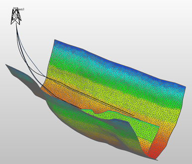
Example of three faults with mapped pore pressure. click to enlarge
To map stresses
- Open the Map Stresses form and under Model, select the fault stability model.
- Under Source type, select the type of object or input (3D Grid, 3D Mesh, Voxel Grid, Wellbore, Faults in Fault Stability Model, or Custom Gradients) that contains your stress input data.
- Under Source, select the object that contains the stress data, for the source types where this applies.
- Under Input type, select how you will provide the stress data by choosing one of the options:
- Principal stresses
- Tensor (JewelSuite)
- Tensor (Abaqus/FLAC3D)
- Enter the stress and pressure information.
- The principal stresses SHmax and Shmin (maximum and minimum horizontal stress respectively) need to be total stresses, with compressive stress positive.
- The azimuth orientation of SHmax, measured clockwise from North.
- Sv, the vertical stress.
- Pore pressure.
- Tensor components defined in the JewelSuite convention. Note that principal stresses need to be total stresses (i.e., stress including pore pressure), with compressive stress positive.
- Pore pressure.
- Tensor components defined in the Abaqus or FLAC3D convention. Note that principal stresses need to be total stresses (i.e., stress including pore pressure), with compressive stress positive.
- Pore pressure.
- Abaqus convention Input stress tensor components are S11, S12, S13, S22, S23, S33. The first number indicates the plane the stress is acting on; the second number indicates the stress direction.
- FLAC3D convention Input stress tensor components are SXX, SXY, SXZ, SYY, SYZ, SZZ. The first letter indicates the plane the stress is acting on; the second letter indicates the stress direction.
- Reference depth The reference depth for the gradients that you enter on the form, i.e., the ground level with respect to the solution's permanent vertical datum (home > Settings > Vertical Datums). In the JewelSuite convention where the value of the Z coordinate is positive downward, the reference depth above 'datum' (e.g., mountain / topography) is negative while the reference depth below 'datum' (e.g., ocean floor / bathymetry) is positive. Any water column is not incorporated.
- Pore pressure gradient Enter the value for the pore pressure gradient.
- Sv / Overburden gradient Enter the value for the vertical stress gradient. The stress needs to be total stress, with compressive stress positive.
- SHmax gradient Enter the value for the maximum horizontal stress gradient. The stress needs to be total stress, with compressive stress positive.
- Shmin gradient ;Enter the value for the minimum horizontal stress gradient. The stress needs to be total stress, with compressive stress positive.
- Azimuth SHmax The azimuth orientation of SHmax, measured clockwise from North (see image under 'Principal stresses' below).
- For Source types that involve a mapping step from another object to the tri-meshes (3D Grid, 3D Mesh, Voxel Grid and Wellbore) you have additional options at the bottom of the form:
- Avoid null values (skip neighbors with null values) If you select this option, any null values are ignored as input. The closest defined area will be searched for and populated. This option works well when undefined values exist in a patchy pattern, but for large areas with undefined values, it may lead to undesired extrapolation. The result of this option is a fully populated output.
- Use interpolation between neighbors (takes longer) If you select this option, a linear interpolation is used for the mapping process, instead of nearest neighbor mapping which is used by default. This produces smoother results, although processing may take a significant amount of time depending on your hardware.
- Click Apply or OK to start the mapping and conversion processes and proceed to the Calculate Fault Stability form. If you have many time steps and/or fine tri-meshes, and depending on factors such as the selected Source Type, the presence of time steps, the resolution of the target tri-meshes, and the performance of your machine, the stress mapping may take a couple of minutes. When the mapping and conversion are finished, the properties can be found in the newly created folder called 'Mapped Stresses' under the fault tri-mesh(es) in the JewelExplorer.
If your input data is described as principal stresses, you can map stresses by selecting Input type as Principal stresses and providing the following data:
Make sure that the value of the Z coordinate is positive downward, i.e., according to the JewelSuite convention. The image below displays the graphical representation of principal stress input parameters (SHmax, Shmin, Sv, azimuth of SHmax) when mapping to JewelSuite convention (shown in gray).
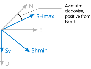
Input parameters for principal stresses when mapping to JewelSuite convention (shown in gray). click to enlarge
To assign input properties for Principal stresses
On the right side of the form, under Stress Properties, select the input properties containing the stress data from the drop-down menus, i.e., Pore pressure, Sv/Overburden, SHmax, Shmin and Azimuth SHmax.
Continue with step 6.
If you have stress data in the form of tensor components in the JewelSuite convention, select Input type as Tensor (JewelSuite). In the JewelSuite convention, the value of the Z coordinate is positive downward.
To use this method, you need to have the following information:
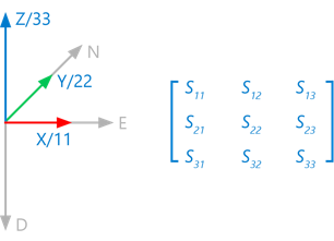
The image below displays the graphical representation of input tensor components in the JewelSuite convention (SNN, SNE, SND, SEE, SED, SDD). The first letter indicates the plane the stress is acting on; the second letter indicates the stress direction.

Input stress tensor components in the JewelSuite convention. click to enlarge
To assign input properties for Tensor (JewelSuite)
On the right side of the form, under Stress Properties, select the input properties from the drop-down menus, i.e., SNN, SNE, SND, SEE, SED, SDD and Pore pressure.
Continue with step 6.
Select Input type as Tensor (Abaqus/FLAC3D) if your stress data consists of tensor components that result from an Abaqus or FLAC3D simulation. In those simulators' convention, the value of the Z coordinate is positive upward. Upon mapping, the data will automatically be converted into the JewelSuite convention, see image below.
To use this method, you need to have the following information:
The image below displays the graphical representation of input tensor components in the Abaqus and FLAC3D convention:
The stress data will be mapped in the JewelSuite convention (shown in gray) as tensor representations on the faults.
Input stress tensor components in the Abaqus or FLAC3D convention. click to enlarge
Conversion from Abaqus/FLAC3D to JewelSuite convention
The selected stresses will be automatically converted from the Abaqus or FLAC3D convention into the JewelSuite convention. In other words, once stresses are mapped to the fault, they are always in the JewelSuite convention. Conversion is required because the Abaqus/ FLAC3D and JewelSuite conventions have their axes (on which the tensor is based) pointing in different directions, as can be seen in the image above.
| JewelSuite convention | Abaqus convention | FLAC3D convention |
|---|---|---|
| SNN | S22 | SYY |
| SEE | S11 | SXX |
| SDD | S33 | SZZ |
| SNE | S12 | SXY |
| SED | – S13 | – SXZ |
| SND | – S23 | – SYZ |
To assign input properties for Tensor (Abaqus/FLAC3D)
On the right side of the form, under Stress Properties, select the input properties from the drop-down menus, i.e., S11, S12, S13, S22, S23, S33 and Pore pressure.
Continue with step 6.
This method is similar to Principal Stresses (see 'Input type = Principal Stresses' below) except that you provide the stress data not as properties, but as gradients relative to a reference level. The stress data is subsequently mapped to the fault nodes based on these gradients.
Enter the following data on the form:
When you have finished entering custom gradients, continue with step 7.